
Ring gear has already been removed, now replacing the worm gear.
1. Remove flange mount motor.
2. Remove thrust bearing cover.
3. Remove three allens holding thrust-to-worm retainer plate, set aside.
4. Remove bolts holding brake-side worm bearing retainer plate, (where the shaft seal is).
5. Remove brake spring, loosen brake shoes off, clear of brake drum. Worm now spins freely.
6. Tug on brake drum, pulling worm out of machine from the brake side. There is a spanner nut, that holds the brake sheave onto the worm. It is recessed, where a spanner wrench won't fit onto it. We could coax it around with a single jack and a punch, but there seems to be no reason to do so, since it looks like the brake drum can come out with the worm together as a unit.
Did all this, but worm gear will not come out of the gear case.
Brake side worm bearing looks like it just presses in, perhaps more force is needed to pull this bearing out with the worm?
Thrust bearing inner race will spin on end of worm, suggesting the thrust bearing is not seized to the worm shaft. Perhaps the worm gear comes out from the thrust bearing end of the machine? Any ideas? Have I missed a something?
Also- Are the sheave shaft bearing caps eccentric? Seems to be no obvious way to adjust the backlash.
"Crown wheel", sure, that makes perfect sense, even though it's the first time I heard that term. If you wanted to take the worm out, without first removing the crown wheel, maybe you could unscrew it as you pull it out? IDK, just wondering.
What are "packers"? Is that what we call "shim" plates? You know, little thin pieces of metal, used to adjust parts of machinery?
This sheave shaft has no shims anywhere, to raise and lower it. On each end of the sheave shaft, there are angled pin-roller bearings, which ride in removeable outter races. These outter races have horizontal bolts, threading into both the machine casting, and the crown wheel cover. The race itself becomes a "fishplate" of sorts, securing the top cover onto the lower machine casting. It is not possible to fit shim stock into this arrangement, to effect any change in ring height. The only possibility would be if the outter races were eccentric, then they could be rotated, and the ring would raise and lower according to the degree of rotation of the outter race(s). But the 6 bolt circular hole pattern means that the adjustment would be in steps, and not infinitely variable. Doesn't seem likely that Otis would do it this way. Of course, the worm has no ability to move vertically either.
Looking at the outter races, there is no apparent eccentricity to them, either.
Weird.
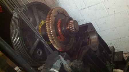
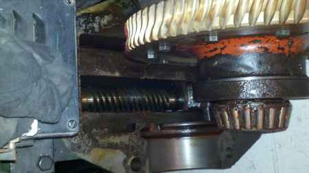
-remove thrust cover
-there is a screw to adjust the worm(is about 1 to 1.5 inch wide), sort of with a half screw head that i think has a tool for it but you can use a flat screw driver to adjust the worm in and out.
-when you have moved the screw to the desired point flip th tab into place to lock the screw down.
- now you generally do this with the counterweight landed and everything still attached.
not saying this is for every machine but it most likely the same.
now when removing the worm you disconnect the collar on the brake drum, remove the thrust cover, with a bin lid underneath to collect the oil, the whole worm should come out the rear end with the crown wheel removed. you may need to undo the ring nut assembly on the thrust end , not sure.
not sure why your replacing the worm but try this and let me know.
cheers mate.
Thanks for checking around, I sincerely appreciate it.
For the backlash adjustment, I don't think this particular machine is the same as you describe, but I will take another look at it tomorrow.
It sounds much easier to take the worm out from the thrust bearing end. I can see how that works- because the thrust bearing is made to be replaced, so it's easier to take out. Whereas the other worm bearing, (closest to brake end of the worm), doesn't generally need replacing, since it doesn't operate under as much end-play stress as the thrust bearing. So the brake end bearing is probably pressed in, which explains why the worm didn't budge, under tension applied from the brake end.
Unfortunately, this machine is facing the wall, so taking the worm out through the back end, (thrust bearing end), isn't a practical option. I wanted to swap in a good (but used) worm, because this worm is somewhat pitted. I don't want the pitting to wear away a good ring gear.
Thanks for your interest!
The idler bearing on the worm at the brake end of the machine is pressed in, and the worm won't go out that end, unless you pull that pressed-in bearing. So if your machine thrust-end is facing a wall, you have to unbolt it from the bedplate, and spin the machine around.
As far as "backlash", I'm referring to the gap between the crown and worm teeth. Maybe it's just confusion of terminology.
As I read your post, I think you are describing the "end play" of the worm, the distance it can slide back and forth horizontally within the machine. At any rate, my 22CT machine worm gear does not have a threaded end, no spanner nut, and no bolt to adjust it in any direction. It has a retainer plate, that locks the worm gear into the thrust bearing inner race. It's held on with three allen bolts, then safety wired.
Someone said that there are no adjustments for the wrom-to-ring engagement.
Going back tomorrow to finish up.
glad it worked out for you vic.
cheers mate.
I learned one more thing about the machine- If the crown or ring gear is not directly over the worm, then the top cover will not go down and mate properly with the machine casting.
Thanks for your help with this. It's great to have someone to bounce ideas off of, and share info. I appreciate your input very much.
Cheers!
cheers.
We saw that the outer sheave shaft bearing races have bolt holes 30 degrees apart, indicating that the bearing race can be rotated, to raise or lower the ring gear mesh into the worm. The adjustment is very slight, by my way of looking at it. I've seen other manufacturers that (relatively speaking) have a tremendous range of adjustment for the backlash. I guess Otis figures that if more adjustment is needed, beyond the design parameters, then you got other worse problems, that shouldn't be compensated for by an adjustment.